Free templateLED circuit diagram
LED circuit
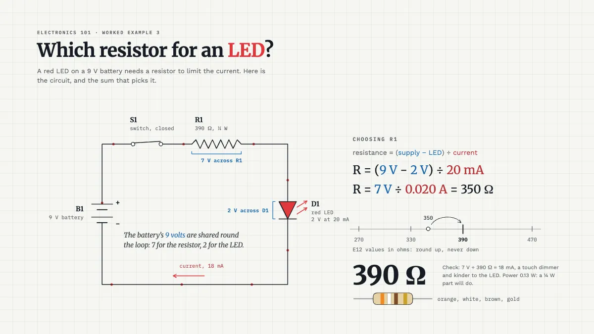
A battery, switch, resistor and LED in standard symbols with current flowing, beside the worked sum that picks a 390 Ω resistor.
Free. It opens in the Motionix editor as your own copy.
Download the pictureWebP, 1200 × 675, free to use. To change the words or colours, open it in the editor.
- Size
- 1920 × 1080 px
- Pages
- 1
- Motion
- Yes, plays live and in GIF or video
- Category
- Technical
What it shows
- Standard circuit symbols
- Current flowing round the loop
- A worked calculation
Good for
How to use it
- Open the template. It becomes a project in your account.
- Change the words, colours and pictures. Every part is an ordinary shape, line or text box.
- Press Play to watch it build, then present it or export it.
What is an LED circuit diagram?
An LED circuit diagram shows how to wire a light-emitting diode to a power source safely, using standard symbols for the battery, switch, resistor and LED. The key part is the current-limiting resistor in series with the LED, sized with Ohm's law: R = (Vs - Vf) / I, where Vs is the supply voltage, Vf the LED's forward voltage and I the current you want through it.
When it helps
- A first electronics lesson, where students build a series circuit and then draw it.
- A maker adding an indicator light to a project and choosing the right resistor.
- Teaching how a supply voltage is shared between parts of a series circuit.
- Checking a design before soldering, so the LED survives its first power-up.
Tips
- Round the resistor up, never down. A slightly larger value makes the LED a little dimmer; a smaller one pushes more current than it is rated for and shortens its life.
- Look up the forward voltage for your LED colour. Red is often around 2 V while blue and white are nearer 3 V, so one resistor value does not suit them all.
- Do not run LEDs in parallel from one shared resistor. Small differences in forward voltage let one LED take most of the current; give each its own resistor.
How to draw an LED circuit diagram
Draw the supply
Use the battery symbol: a long plate for positive and a short plate for negative. Label it with a reference and a value, such as B1 and 9 V.
Add the switch and resistor
Draw them in series along one side of the loop. The resistor is a zigzag in American style or a plain rectangle in IEC drawings; label it R1 with its value and power rating.
Draw the LED the right way round
The LED is a triangle pointing in the direction of conventional current, with a bar on the cathode side and two small arrows for light. The bar faces the negative terminal.
Close the loop
Wire the LED back to the negative terminal so every part sits in one series loop. Mark the direction of current, from positive round to negative.
Work out the resistor
Subtract the LED's forward voltage from the supply and divide by the current. For a red LED of about 2 V at 20 mA on 9 V, (9 - 2) / 0.02 gives 350 Ω.
Round up to a real value
Resistors come in standard series such as E12. Take the next value up, 390 Ω here, then check the current, about 18 mA, and the power, about 0.13 W.
FAQQuestions
Common questions.
Why does an LED need a resistor?
An LED cannot limit its own current. Once the voltage across it passes its forward voltage, the current rises very steeply, and without a resistor it can quickly exceed the rating and destroy the LED. The series resistor sets the current to a safe value.
What is the forward voltage of an LED?
It is the voltage an LED drops while it is conducting and lit. It depends mainly on colour: red and yellow LEDs are often around 1.8 to 2.2 V, while blue, white and many green LEDs sit around 2.8 to 3.3 V. The datasheet gives the exact figure.
Which way round does an LED go?
The longer leg is the anode, which connects towards positive; the shorter leg, the cathode, connects towards negative. The cathode side is often marked by a flat edge on the rim of the LED. On a circuit symbol, the bar marks the cathode.
More technical templates
Architecture, networks, circuits, plans and data.